Proto I/Os Arduino Rev. A
This is a project included in a series of projects ive decided to start, to reduce the hadware set up time for prototype developing.
It is an Arduino shield.
It has eight LEDs each one with a 470Ω resistor in series to pins zero to seven, also known in arduino has digital outputs.
Then it has four push buttons, each one with a 10KΩ resistor pull-up, meaning this buttons are ON with 0V its a negated input (Ī), also each button has a 10nF capacitor to GND that works has debouncing, thus a debouncing subroutine is optional for the buttons.
Connected to digital output 13 there is a 1KΩ resistor that drives a BC817 NPN transistor which grounds a buzzer, theres is also a small capacitor between the buzzer pins to filter bouncing.
Features
- Eight LEDs on pins 0–7 (with 470 Ω resistors)
- Four push-buttons with 10 kΩ pull-ups and 10 nF debounce capacitors
- Buzzer driven by transistor BC817 via pin 13
- One-wire devices like DS18S20 temperature sensor
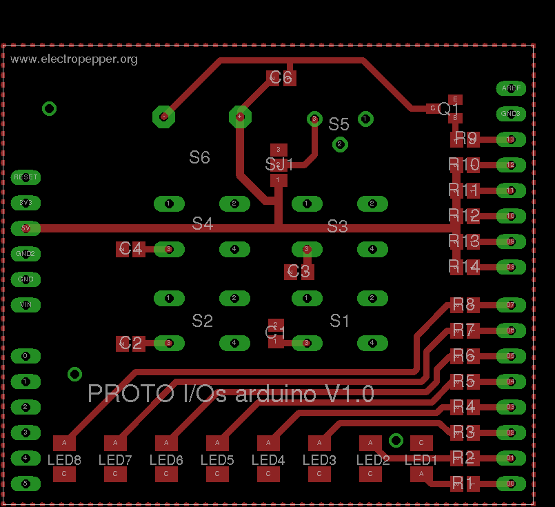
Schematic
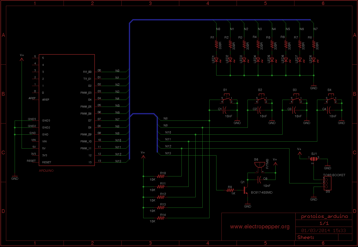
This board was design in Eagle, here is the schematic and the PCB.
Placement & Parts List
BOM (Bill of Materials)
| Reference | Value | Package |
|---|---|---|
| R1–R8 | 470 Ω | R0805 |
| R9 | 1 kΩ | R0805 |
| R10–R14 | 10 kΩ | R0805 |
| C1–C4, C6 | 10 nF | C0805 |
| Q1 | BC817 | SOT-23 |
| LED1–LED8 | LED | KA-3528ASYC |
| S1–S4 | Button | B3F-10XX |
| S5 | DS18S20 | 3-pin socket |
| S6 | Buzzer | - |
In the S5 there is a socket for 3 pins packages usually TO-92, being pin 1-GND, pin 2-DATA and pin 3 connects to SJ1 which is a jumper to be connected to either GND or VCC, in case of 1 Wire devices if you connect SJ1 to GND the device will work in parasitic mode, getting power from the DATA line, otherwise you connect it to VCC to get the device powered.
Most of the components can be found in farnell, But if you really want to build this and run into problems, you can always contact me, i still have a lot of spare parts.
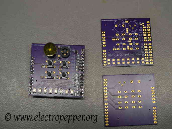
I have made the PCB with the Osh park service, here is the clean and built PCBs :
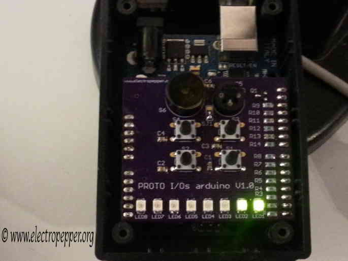
And here is a final picture of the board connected inside a box.
Demo Video
Created on 20-04-2014